| Home Page |
| Latest News |
| GB3FM |
| GB3FN |
| GB3FNM |
| GB3FRS |
| GB3FX |
| GB3SN |
| Coverage |
| The Group |
| Supporters |
| Constitution |
| How to Join |
| Help Us! |
| Radio Links |
| Site Tour |
| Contact Us |
GB3FM - GB3FN - GB3FNM - GB3FRS - GB3FX - GB3SN
GB3FM - Specification
GB3FM is located on a site 3 km North of Farnham, Surrey, UK at; National Grid Reference; SU821494
QTH Locator; IO91OF
The site is 187m above sea level and is shared with GB3FN and GB3FX - the group's 70cm and 6m repeaters - and the GB3FNM beacon. It operates as a combined beacon and repeater on the 23cms band. It has been operational since 13 March 1988. It runs about 5W ERP horizontally polarised from an Alford Slot. It used vertical polarisation between 1997 and 2007, but reverted to horizontal polarisation in late 2007.
The repeater currently uses a single antenna, with the receiver and transmitter combined in a duplex filter. There are two antennas on the tower, but one has become faulty in the years following the last antenna rework in 2008, necessitating the single antenna approach. Some recent fall-off in signal was traced to connections in the site, and currently the repeater is operating to the best of its capabilities.
A second temporary Alford Slot antenna has been installed low down on the tower for emergency use, but coverage is much less with this antenna due to the lower height of the antenna and the height of the surrounding trees.
NOTE: The FSK keying sequence is occasionally out of action, as a backup oscillator is occasionally used on site while engineering has been carried out.
A brief specification of the repeater - when operating with normal antennas - follows.
| Transmitter Section | |
| Transmitter | Based on Storno CQF9662 exciter, modified to provide 3x output frequency, plus on frequency Microwave Modules PA. |
| RF Output | 5W |
| Effective Radiated Power | 5W |
| Transmit frequency | 1297.050 |
| Frequency stability | Better than 100 Hz Typically better than 30Hz |
| Receiver Section | |
| Receiver | LMW Electronics convertor, + CQF9774 receiver front end + Storno M900 IF |
| Sensitivity | Better than 0.7 V EMF (0.35 V "PD") |
| Receive frequency | 1291.050 MHz |
| Receiver AFC | Up to 7 kHz |
| Antenna System | |
| TX Antenna | Home made Alford Slot, approx 6dBd gain, approx 20m AGL |
| RX Antenna | Same as TX antenna. |
| Feeder | LDF5-50 (RX), part LDF5-50 and part LDF-4-50 (TX) (we ran out of 5-50 before the bottom of the tower) |
| Polarisation | Horizontal |
| Duplex Filtering | Four cavity notches are available, two for each leg, 3/4
wave at 23cm, from UHF Motorola base station plus some
critical length cables. A single home made pass cavity is in the transmit leg to clean up transmit noise slightly. Desensitisation of RX by TX: none. |
| Frequency reference | Motorola ovened 5MHz oscillator Note: this is not shared with 'FN or 'FX (because it is keyed to provide the FSK callsigns) |
| Logic Control | |
| Logic | PIC based by G4EPX |
| Access | 1750 40Hz tone for minimum of 200msec |
| Reaccess | By carrier. The repeater sends its callsign every valid access and reaccess (after about a second). |
| Timeout | 8 mins |
| Reply signal | 2333 Hz decaying 'ping' (unless replaced by frequency or signal indication) |
| Frequency indication | 'Ping' replaced by 'H' or 'L' sent in 1167Hz Morse for input signal more than approx 5kHz high or low of nominal input frequency respectively |
| Signal indication | If 1750Hz tone burst is sent within 2 seconds of start
of transmission (except the accessing transmission), the
repeater will replace the 'ping' with a Morse numeral; 1-8
and N (for 9). S1 ranges from squelch threshold to
about 1uV EMF, successive S readings given at
approximately 3dB increases of signal. Note: this is
approximate, not calibrated! Note: the signal indication will not be given if an input signal is more than 5kHz off frequency, and qualifies for an 'H' or 'L' instead. |
| Identification | Callsign appoximately every 2 minutes at 875Hz out of
use, and at start of every over at 1167Hz when in use. QTH locator (IO91OF) and location ("Farnham Surrey") sent every alternate 6 minutes out of use using FM. FSK callsign every 20 seconds, except when the FM identification is sent, and except when in talkthrough. The FSK callsign sequence can be occasionally out of operation due to engineering work. |
| Tone suppression | 40dB in notch filter switched in after 200 msec |
| Subaudible tone | 100Hz transmitted at 500Hz deviation during talkthrough.
No receiver CTCSS access. Note that this stays with the 'original' 23cm plan for CTCSS, and does not follow the regional CTCSS frequency plan. It features as an 'S' ('special') on RMG repeater lists because of this. No one has complained about lack of a regional tone yet... |
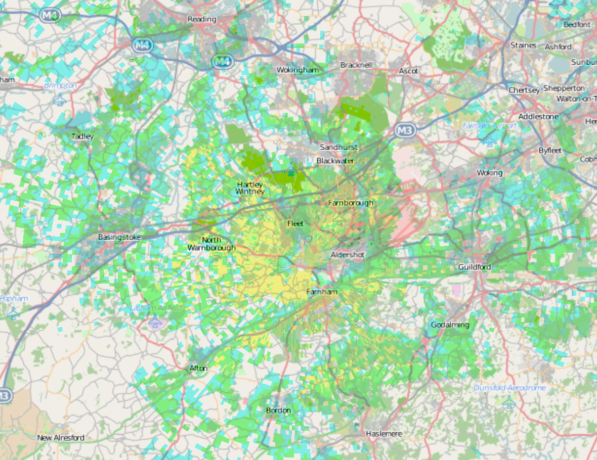
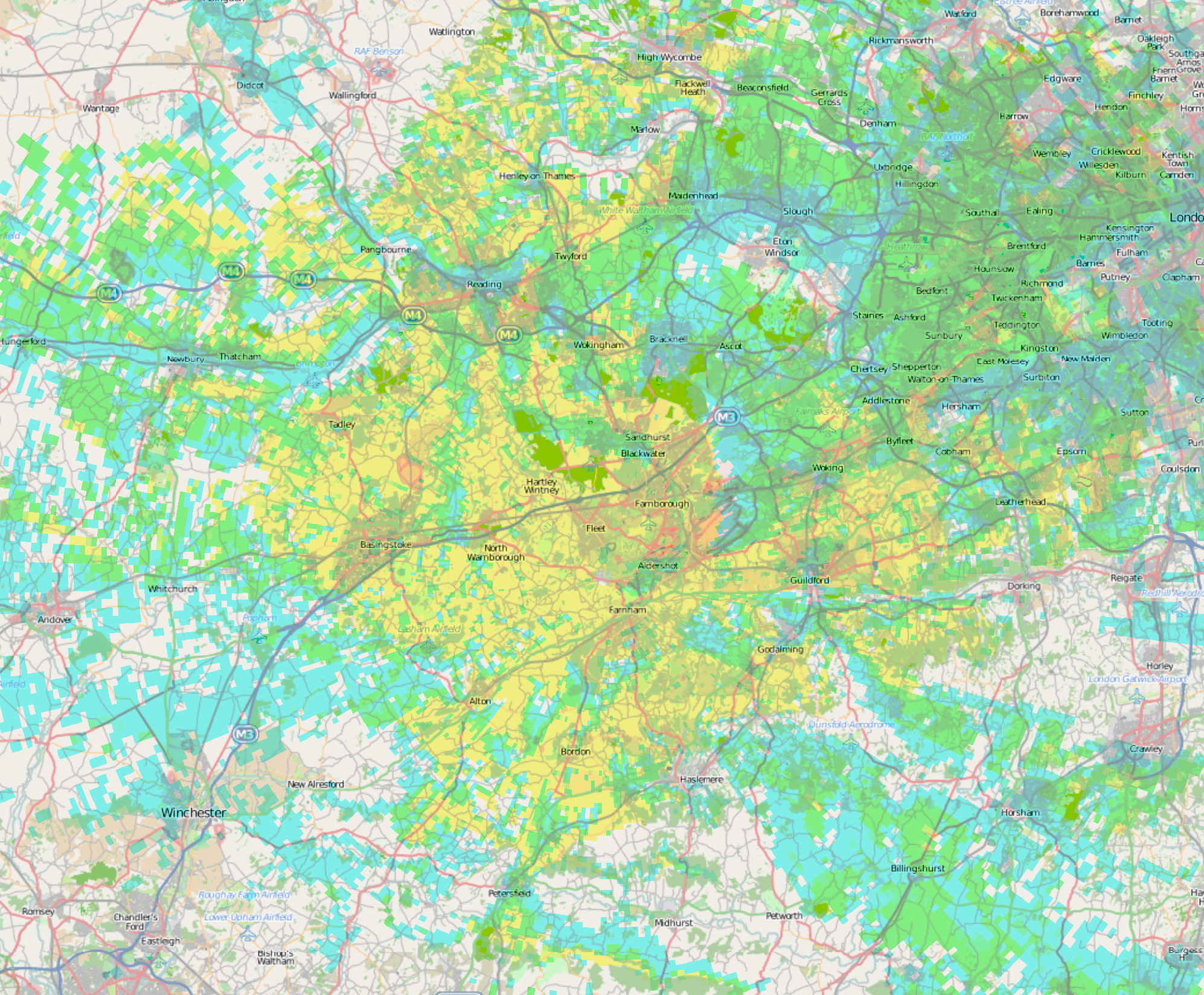
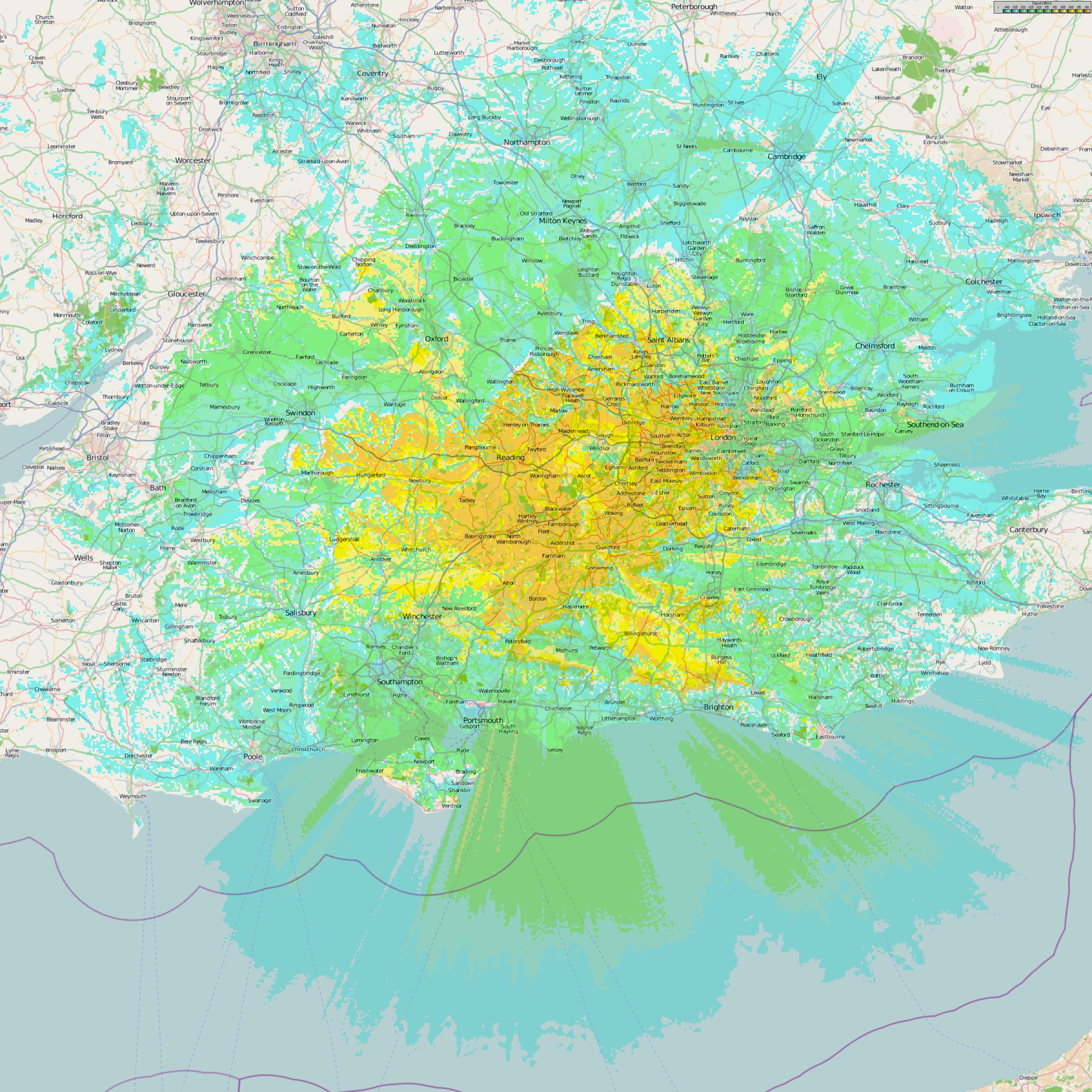
Coverage Maps
Coverage predictions are likely to be more approximate at 23cm than for our other repeaters.There are three maps plotted:
GB3FM mobile - whereas 23cm mobiles are few and far between, this gives an idea of where the repeater might be heard. The repeater should be audible over the yellow area with a simple setup, such as a portable inside a car (perhaps on the dashboard). The green and blue areas will probably need an external antenna, such as an Alford slot on top of the car; the blue area probably audible only when there are not local obstructions near the mobile.
GB3FM fixed - this is intended to give an idea where a fixed station with an outside aerial may be able to hear the repeater. The yellow area has a good probability of success and the green area should also be achievable for a fixed station with a reasonable aerial without too much local obstruction. The blue area may still be good to receive the repeater, but is likely to need a good aerial and possibly some careful location of the aerial to avoid local obstructions.
GB3FM beacon - this gives an indication of where the repeater might be heard by a fixed station listening for beacons. The light orange area gives an indication where a station with reasonable aerial at rooftop height should be able to receive the repeater with an FM receiver, and depending on how much the receiving site is in the clear, its antenna gain and so on, it may be receivable on an FM receiver in the dark and light yellow areas. An SSB or CW receiver should be able to receive the repeater over the yellow areas and may be able to receive the repeater in the green areas. The blue areas would really need an exceptional setup to hear a signal – a high gain aerial, high up in the air, probably with mast head pre-amp, such as might be used on hilltops for contests.
| Top of Page | Home Page | GB3FX Specification | GB3FN Specification |