| Home Page |
| Latest News |
| GB3FM |
| GB3FN |
| GB3FNM |
| GB3FRS |
| GB3FX |
| GB3SN |
| Coverage |
| The Group |
| Supporters |
| Constitution |
| How to Join |
| Help Us! |
| Radio Links |
| Site Tour |
| Contact Us |
GB3FM - GB3FN - GB3FNM - GB3FRS - GB3FX - GB3SN
GB3FX - Specification
GB3FX is located on a site 3 km North of Farnham, Surrey, UK at; National Grid Reference; SU821494
QTH Locator; IO91OF
The site is 187m above sea level and is shared with GB3FN and GB3FM - the group's 70cm and 23cm repeaters - and the GB3FNM beacon. It has been operational since 10 October 1997.
A brief specification of the repeater follows.
Some philisophy behind the design: the coverage from well sited 6m repeaters is tremendous, although the band is still quiet. 6m is quite sensitive to electrical interference, for example ignition noise from older petrol engines, which is why the receiver has an AFC loop to try and minimise the effect of this. The logic has been designed to try and be helpful to users without annoying them too much. That's why the repeater has the simple 1 sec hang on initial access - if someone really wants to try to get in without giving his or her callsign, they can get brief confirmation without subjecting other listeners to lots of morse code! The signal strength indicator allows a station to judge their signal if there is no one else around. The overdeviation indicator is fairly unobtrusive - but as it's set quite high, stations really should adjust their deviation so as not to hit it, if they are going to avoid distortion and squelch closure on deviation peaks. We also recognised that the CTCSS-only access on 6m would cause some stations problems as they adjusted or found the right tone, which is why stations without the correct CTCSS tone can get a few seconds of low deviation talkthrough - hopefully enough for others to help them set up correctly.
The repeater runs a single dipole about 15m above ground.
We originally used a duplexer made out of Heliax from the WB5WPA design. It worked very well, cost virtually nothing, but because we only had LDF5-50 Heliax, was a bit lossy especially on transmit. Thanks to the extreme generosity of Rupert, G4XRV, who donated both his time and the materials, we now have a custom made duplexer made with real helical filters, which has been running since January 2003. And a good couple of dB less loss. This has helped increase the ERP slightly.
The repeater has had a couple of improvements over the years as well, especially in the receiver section where the IF and front-end have been modified further to improve the sensitivity. We are now limited by the level of intermodulation products that come from another site across the road, which doesn't seem to have the greatest filtering in the world on its transmitters. This also prevents us putting out more TX power, although the box itself is capable of it.
From 2009, like GB3FN, the repeater has been modified to transmit CTCSS tone at all times, including when sending its callsign when out of use. This allows mobile operators to drive around using a tone squelch to cut out the high levels of noise and interference on 6m, whilst still hearing periodic callsigns as a confidence and coverage check. This is not to everyone's taste, but the majority of those surveyed prefer this. Note that the CTCSS tone is not sent during callsigns sent after a timeout - this is to avoid any latch up situations involving local intermodulation sources close to the site.
| Transmitter Section | |
| Transmitter | Storno CQF9334 modified from 70MHz band |
| RF Output | 28W |
| Power into feeder | 16W |
| Effective Radiated Power | 14W |
| Frequency | 50.810 MHz |
| Frequency accuracy | Better than 3 Hz Typically better than 1Hz |
| Receiver Section | |
| Receiver | Storno CQF9334 modified from 70MHz band |
| Frequency | 51.310 MHz |
| Sensitivity | 0.3 V EMF (0.15 V "PD") for 12 dB SINAD |
| Sensitivity into filter | 0.4 V EMF (0.2 V "PD") for 12 dB SINAD |
| Antenna System | |
| Antenna | Homebrew dipole |
| Height | 15m above ground at bottom of antenna (top of tower) |
| Feeder | LDF4-50 |
| Polarisation | Vertical |
| Filter system | Helical duplexer using two notches in each leg built by G4XRV |
| Desensitisation of RX by TX | Less than 1dB |
| Frequency reference | Motorola ovened 5MHz oscillator (Shared with GB3FN, separate from GB3FM) |
| Logic operation | |
| Access | 82.5Hz CTCSS tone (RSGB tone D) |
| Reaccess | Carrier with CTCSS |
| Timeout | 4 minutes |
| Identification | Callsign sent; Every 5 minutes as beacon On full access - from cold after 5 seconds modulated transmission On shutdown - after a QSO On timeout (every 20 secs) |
| Reply signal | Tone pip(normally) "B" if operating on standby batteries "T" (long) after timeout |
| Keying frequencies | 1092 Hz (normal callsign) 546 Hz (timeout callsign) |
| Other characteristics | |
| Tone frequency of pip reply signal varies with signal
strength, from greater than 2kHz if signal is 1 V EMF or
more, to 600Hz for threshold. Less than 2kHz indicates to
mobiles that faded signal is marginal. A dual rate sample
and hold circuit smooths out variations over last few
seconds of transmission. The receiver has limited range ( 500Hz) AFC operation. Callsigns suppressed on access and shutdown after repeated access, or no QSOs. Audio muted by 20dB with no subaudible tone; allows signals with no or incorrect CTCSS to be heard quietly for maximum 10 seconds. Full audio "coast" timer allows full audio to be heard up to 1 sec after CTCSS loss (allows decoder to be talked out by weak signal or overdeviation). Overdeviation signalled by short audio mute and low level 546Hz pip. Reaccess possible in timeout, needs either carrier without CTCSS over the top, or repeated keying on and off for a couple of seconds to shut down the tone decoder. |
|
| Battery lifetime | In excess of 24 hours of mains interruption given normal use patterns. |
| Battery type | Dryfit 12V (2 x 6V) 110Ah |
The repeater is reciprocal with a mobile running 12W and a receiver with 0.5 V EMF (0.25 V "PD") sensitivity.
Coverage Maps
As with GB3FN, the map has been plotted using the excellent Radio Mobile program from VE2DBE. It shows expected mobile coverage, with some dependency on local conditions and the abilities of the mobile installation.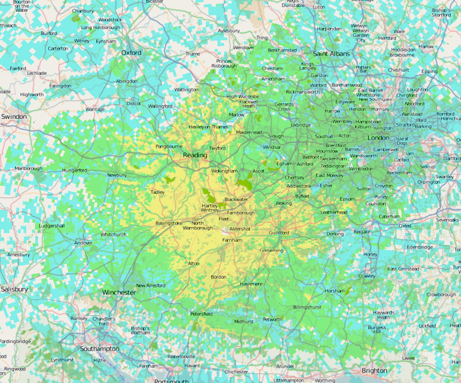
Yellow shows a strong signal, and this area should be
workable for most mobiles.
Green should still be workable for most mobiles unless the
installation uses a short antenna, and unless there are local
obstructions or noise sources.
Blue shows marginal coverage, where mobiles in relatively
unobstructed conditions may be able to use the repeater, depending
on the tolerance of the operator to noise.
Varying antenna efficiency and background noise on 50MHz make the map a little less predictable than at higher frequencies. (Diesel engined cars without CD players do better than petrol engined cars with the CD going - 'FX's output seems to be close to a harmonic of a crystal used universally in CD players!) Many mobiles will achieve somewhere between the two - depending on which direction they are pointing in and so which direction their antenna works best in.
| Top of Page | Home Page | GB3FM Specification | GB3FN Specification |