|
FARNHAM VHF GROUP
GB3FM - GB3FN -
GB3FX - GB3SN
The GB3FNM Beacons
The group also hosts microwave beacons on behalf of the UK
Microwave Group. One beacon is currently active:
| |
5.760 920 GHz |
(ERP = +17dBW) |
It is hoped that the 24GHz beacon, which ceased operating in recent years, will be replaced
at some time. The 2.3GHz beacon is likely to move to another site (and callsign).
Beacon descriptions
 |
The active beacons nominally provide omni-directional coverage subject to variations in the
antenna pattern. Where possible the antennas are oriented to favour directions up-country
and towards the continent.
The beacons provide a useful resource for propagation monitoring and enable microwave operators
to check their receiving equipment.
The equipment consists of indoor units (IDU) which include the power supplies, keyers, stable
frequency references and intermediate or final frequency generation. The intermediate frequency
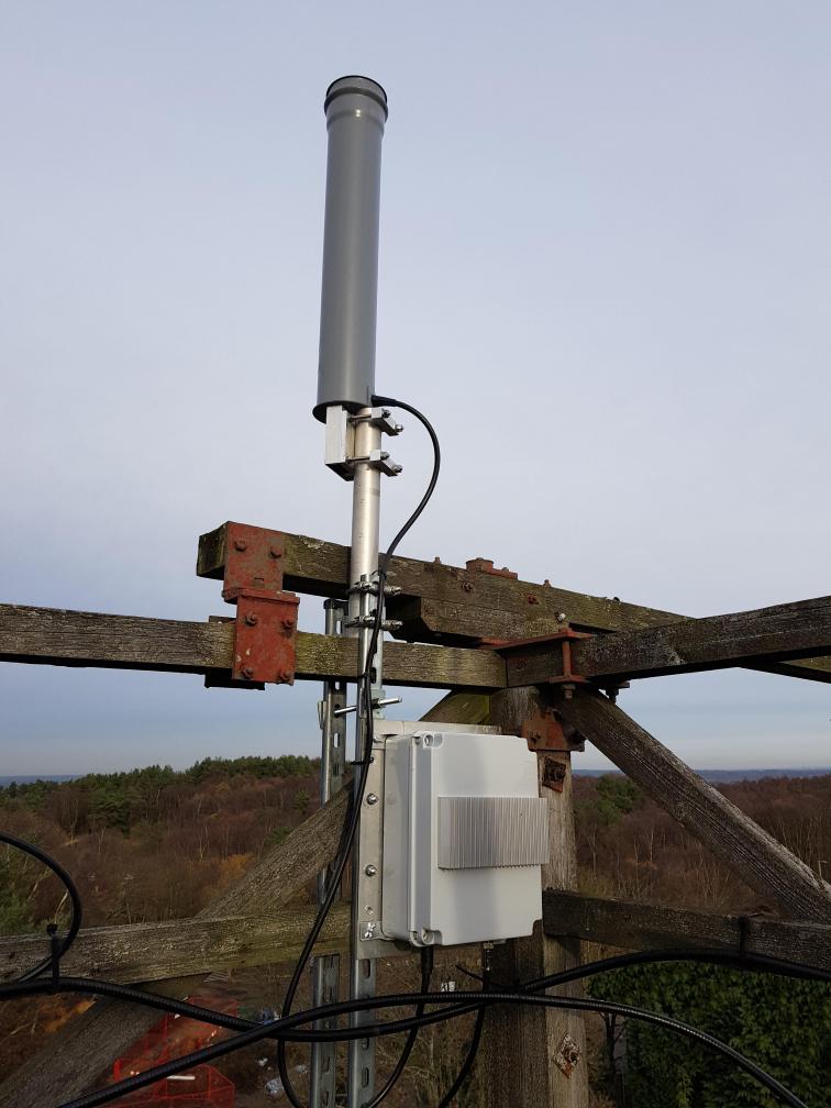
for the 5.7 GHz beacon and power are supplied to the corresponding mast mounted Outdoor Unit
(ODU) via coaxial cables. Since early 2010, the OCXOs have been locked to the 5MHz reference
used for the GB3FN and GB3FX repeaters, to give improved frequency stability.
All the beacons use slotted waveguide
antennas which produce a polar diagram in the form of a four
leaf clover with approximately 10dB of gain in the main pair
of lobes (180 degrees apart) and 6dB gain in the minor lobes
(at right angles to the main lobes). The nulls are at
approximately 0dB. The main 5.7 GHz beacon lobes are aimed
ENE/WSW while the minor lobes are at 90 degrees to these,
i.e. NNW/SSE. The 5.7GHz antenna is housed in a separate
radome connected to the 5.7GHz ODU by a short length of low
loss cable.
|
Top of Page
|